

- Home
- About Us
- Products
- Rohmann Eddy Current
- Secu-Chek UV-LED Lamps
- Sonatest
- MR Chemie
- NOVO DR
- Hoffmann Tam Panels
- Desoutter Industrial Tools
- Novotest
- Integrated Design Tools (IDT Vision)
- Dakota NDT
- DeFelsko Corporation
- AVIONICS
- Sonotec Ultrasonic Solutions
- Sonotec Ultrasonic Hand-Tools
- G.A.L. Gage Company
- Western Instruments Inc.
- Esders Gas Technology
- Yoancomposite
- Hinode Electric
- Services
- News
- Contact Us

 (65) 6878 0608  (65) 6878 0609 |

|
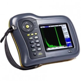
Masterscan D-70
|
Overview
The Masterscan name has always assured the technician of robust instrument construction combined with exceptional performance.
The Masterscan D-70 offers the inspector a fully capable and functional set of tools and software for inspection across all applications. Capabilities include encoded B-Scan, Advanced Thickness logging and Dryscan capability in a portable enclosure.
Features can be added and upgrades performed in the working environment, reducing downtime and increasing working flexibility. High levels of near surface resolution, penetrating power (450V pulser – square and spike) and excellent signal to noise ration are key functions in the Masterscan range.
Typical applications are Weld Fabrication, Corrosion Detection, Composite Inspection, Bond Testing, Forgings and Castings, Power Generation (including EMATS) and general UT inspection.
Features
1) Reliable, Rugged & Robust
An instrument’s ability to perform in harsh environments with proven reliability is an important aspect of flaw detector ownership and this is enhanced by the Masterscan’s outstanding battery performance which is up to 10.5 hours from full charge. The Masterscan’s enclosure is constructed using automotive grade impact resistant materials, offering excellent water resistance. Explosive Testing MIL810-G standards have been passed, together with environmental testing which has confirmed the instrument fully functioning at temperatures above 55ºC. The Masterscan D-70 has a colour transflective VGA display and maximum readability is achieved through adjustable brightness and the choice of 9 colour palettes, including black-on-white LCD emulation mode.
2) Advanced Defect Sizing Tools as Standard
Weld and pipe inspection are major applications for the Masterscan D-70 and they are equipped with the latest software tools for defect sizing. The use of integrated sizing software reduces analysis time and speeds inspection. Multiple standard sizing techniques are essential for service companies working to different customer standards, especially as service work becomes more international and operators are required to work to different codes.
Sizing Techniques and Software Options include:
- DAC (Standard)
- Split DAC & DGS/AVG (Option)
- TCG (Option)
- Backwall Echo Attenuation (BEA) Option (requires TCG)
- AWS (Option)
- AVG/DGS (Option)
- API (Option)
- Interface Trigger (Option)
- Corrosion Software (Option)
- Dryscan Function (Option)
3) UT-Lity Data Management Software
UT-Lity software provides everything you need to manage your inspection data. The standard version is FREE with every instrument and gives you the ability to view, move and manage Calibrations, A-Scans, B-Scans and Thickness Logs both on the instrument and on your PC. With UT-Lity you can also create customised inspection report templates, cut-n-paste information to other applications and create printable pdf documents.
- Load, store, manage files both on the PC and on a connected flaw detector
- Save, analyse, colour code and export thickness logging data to spreadsheets/asset management software
- Update the Flaw Detector and Firmware as and when updates become available on our website
Specification
| Test Range | 0-1mm (0.04in) up to 0-20,000mm (787in.) in steel at 5930m/s (19455f/s) |
| Velocity | 256 – 16000m/s continuously variable |
| Probe | Zero 0 to 1000μs |
| Delay | 0-20,000m (800in) in steel at 5930m/s |
| Gain | 0 to 110dB adjustable in 0.1, 0.5, 1, 2, 6, 14 and 20dB steps |
| Test Modes | Pulse echo and transmit/receive. Single Crystal, Double Crystal and Pitch-Catch |
| Damping | 50 and 400Ohm damping selectable |
| Pulser | 100-450V -ve spike and square wave. Pulse Width from 30nS to 2500nS. Rise/Fall times <5nS into 50R load |
| P.R.F. | Adjustable 5Hz to 6kHz. External sync also available |
| Screen Update Rate | 60Hz |
| Rectification | RF, Full wave, +ve half-wave and -ve half-wave |
| Frequency Range | 8 selectable filter bands. i) 100kHz – 500kHz ii) 200kHz – 800kHz iii) 0.4MHz – 1.6MHz iv) 1.4MHz – 3MHz v) 3MHz – 8MHz vi) 7MHz – 15MHz vii) 9MHz – 21MHz viii) 1.6 MHz – 33 MHz (Wideband) Additional tuned low frequency pre-amp with Dryscan option |
| System Linearity | Vertical = 0.5% Full Screen Height (FSH). Horizontal +-0.2% Trace Full Screen Width (FSW) |
| Reject (Selectable) | Up to 80% Linear reject (removes baseline noise without affecting indication amplitude) Or Up to 50% Suppressive reject (increase zero offset and reduces amplitude of all echoes) LED Warning when active. |
| Units | Metric (mm), inch (in) or microseconds |
| Display | Colour Transflective VGA (640 x 480) TFT. Display area: 116.16 x 87.2mm (4.57 x 3.43in). A-Scan Area: 400 x 510pixels (normal), 460 x 620 (FS). Colours: 9 colour options with variable brightness. |
| Gate Monitor | Two independent gates for measurement and monitoring. Start and width fully adjustable over the entire range of the instrument. Levels adjustable from 0% to 100%, positive or negative triggering on each gate with audible & visual alarms. Gate resolution is 5nS. |
| Zoom | Expands range and delay to cover the area set by Gate 1 start & width controls. |
| AGC | Automatic Gain Control automatically sets the signal in Gate 1 to a level between 10% and 90% FSH, tolerance between 5% and 20%. |
| Measurement Nodes | |
| Mode 1 | Signal monitor, Gate alarms can be active but no measurements are displayed |
| Mode 2 | Depth and amplitude of first signal in gate |
| Mode 3 | Echo-Echo distance measurements |
| Mode 4 | Trigonometric display of beam-path, surface distance (including X-offset) and depth of indication from the inspection surface together with echo amplitude. Curved surface correction can be applied for convex and concave surfaces. Half-skip can be indicated on screen. |
| Mode 5 | Gate to Gate distance measurement |
| Mode 6 | Flank to Flank |
| Mode 7 | Beam Angle, calculated from beampath, hole radius and hole centre depth. |
| Measurement Display | Live display and updates on screen at 3 times per second. Large display of a single measurement available. |
| Contour | Trailing-Edge slew-rate control to reduce half cycles in rectified modes. Selectable from one of 6 levels. |
| Waveform Smoothing | Select from: i) None (both min and max values are displayed in the A-Scan) ii) Fill (Min values set to baseline value, produces a solid A-Scan) iii) Smooth (min values ignored, produces a clear outline A-Scan) |
| Persistence | Causes previous A-scans to “fade out” at a user-determined rate |
| Auto-Cal | Provides automatic calculation of velocity and probe zero from 2 reference echoes |
| Reference Waveform | Displays a previously stored A-log in a colour different from the active display: enabling a quick visual check of the differences |
| Clock | Built in, battery-backed RTC keeps time and date. Visible on the status line, always stored with Panels, A-logs etc. |
| Internal Memory | 4GByte storage available for A-scans, panels, T-logs, B-logs etc. 450,000 Panels, 200,000 A-Logs, 300,000 B-Charts, 440,000 T-Logs |
| Active Peak Memory | Retains all A-scans on screen for echo-dynamic pattern analysis, with the active A-scan displayed in a separate colour |
| Notes | Alphanumeric labelling for panel stores, A-logs, B-logs etc. |
| Display Freeze | Hold the current waveform on screen for off-line processing |
| Help Key | Shows software and hardware information |
| Language Support | Multiple languages are selectable from a list including: English, French, Spanish, Russian, Chinese (Modern). Others are available on request |
| Encoder Connection | Lemo min 4-pin connector |
| Video Output | Factory Option |
| Proportional Outputs | Available on 700M. |
| External Sync | Available on 700M. |
| USB Connection | Internal storage shown as Memory Device. |
| Transducer Sockets | BNC or LEMO (factory option). |
| Power | Battery life for MS700 is 13.5 hours and for D-70 it is 10.5 hours. |
| Charger | 100-240 VAC, 50-60Hz. |
| Environmental | Designed to meet IP67 |
| Temperature | Operating -10°C to 55°C (14°F – 131°F). Storage -40°C to 75°C (-40°F – 167°F) |
| Size | H172mm x W238mm x D70mm (6.77in x 9.37in x 2.75in) |
| Weight | 1.7 kg (3.7lbs) with battery |
| Warranty | 2 year |
| Extended Warranty | Sonacover – extended 5 year warranty, including 4 calibrations. |
| Calibration Standard | EN 22232-1 2020 (Detailed Specification available on request) |
| Standards | Vibration to 514.5-5 Proc 1 Annex C Fig 6 Shock 516.5 Proc 1 15g/6ms Explosive atmospheres – MIL-STD 810G Method 511.5 Procedure I |