

- Home
- About Us
- Products
- Rohmann Eddy Current
- Secu-Chek UV-LED Lamps
- Sonatest
- MR Chemie
- NOVO DR
- Hoffmann Tam Panels
- Desoutter Industrial Tools
- Novotest
- Integrated Design Tools (IDT Vision)
- Dakota NDT
- DeFelsko Corporation
- AVIONICS
- Sonotec Ultrasonic Solutions
- Sonotec Ultrasonic Hand-Tools
- G.A.L. Gage Company
- Western Instruments Inc.
- Esders Gas Technology
- Yoancomposite
- Hinode Electric
- Services
- News
- Contact Us

 (65) 6878 0608  (65) 6878 0609 |

|
Ultrasonic, TOFD and phased array flaw detector and thickness gauge
|
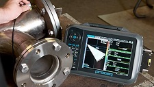
Detect flaws, measure thickness and determine material properties in components including forgings, composites, plastics and welds
Incorrect or missed inspections put your component’s integrity at risk. Proceq’s advanced ultrasonic flaw detectors and thickness gauges provide intuitive measurement solutions to ensure part integrity. The Proceq Flaw Detector 100 is a flexible high tech ultrasonic inspection instrument. The basic UT model can be upgraded with the Ultrasonic Time of Flight Diffraction (TOFD) and Phased Array (PA) modes anytime and anywhere, even on site. The Zonotip, with its shockproof housing and fast processor, delivers reliable thickness measurements of materials including ferrous and non-ferrous metals, polymers, composites, glass, ceramics and epoxies.
| Model |
Proceq Flaw Detector 100 UT |
Proceq Flaw Detector 100 TOFD |
Proceq Flaw Detector 100 PA 16:16 |
Proceq Flaw Detector 100 PA 16:64 |
Zonotip(+) |
| Description | The Proceq Flaw Detector 100 has a large display to show the A-scans from the two onboard channels. The use is simple and efficient due to wizards and an active help file. 3D scan plans assist in creating inspection procedures and analyzing the results. | The upgrade to Proceq Flaw Detector 100 TOFD enables the TOFD application to deliver the highest performance. Two channels make it possible to inspect thick parts in a single pass. High frequency probes can be used to get accurate defect sizes. | The upgrade to Proceq Flaw Detector 100 PA 16:16 will bring a broad spectrum of applications that can be setup, performed and analyzed using the inbuilt wizards and user guides. For users wishing to learn about the phased array capabilities, or to show a sectoral scan. | The upgrade to Proceq Flaw Detector 100 PA 16:64 allows even more flexibility in your setup. The additional multiplexing is beneficial for performing L-scans in corrosion mapping and when testing the integrity of large composite panels | The Zonotip is for thickness testing of a wide range of materials. Its high-contrast color display ensures visual control of the inspection process. The Zonotip+ includes a smaller single-element transducer which is suitable for measuring in areas where access is limited. |
| Your Benefits |
Simple code to upgrade anytime to TOFD and Phased Array (PA) Bandwidth down to 200 kHz to test on attenuative materials, plus 2 axis encoding to record data Improved traceability with automatic reporting |
Only pay for the options you need Advanced features such as lateral wave removal and lateral wave straightening Perform two-channel TOFD inspections simultaneously |
High level of performance for conventional portable flaw detection with the power of phased array A, B, C, True Top and End scans imaging capabilities cover many applications The 3D scan plan helps to visualize the phased array beam coverage in the component |
Compatible with any 64 element linear phased array probe Simple 30 second configuration C scans can be displayed in amplitude or depth. With merged C scans, data is displayed for all inspection passes in the same view |
Easy to setup and use The A scan mode allows a more in-depth analysis of the reading (Zonotip+ only) Rugged housing for difficult weather conditions (frost- and heat-proof) |
| Configuration | 2 UT Channels | 2 UT Channels | 16:16 Channels | 16:64 Channels | 1 UT Channel |
| Transducer Socket | Lemo 1 and BNC | Lemo 1 and BNC | UT/TOFD: Lemo 1 and BNC PA: I-PEX | UT/TOFD: Lemo 1 and BNC PA: I-PEX | Lemo 00 |
| Plus Voltage | -100 to -450 V (in steps of 10 V) | -100 to -450 V (in steps of 10 V) | UT/TOFD: -100 to -450 V (in steps of 10 V)PA: -25 to -75 V (in steps of 5V) | UT/TOFD: -100 to -450 V (in steps of 10 V)PA: -25 to -75 V (in steps of 5V) | |
| PRF | 1 to 1500 Hz | 1 to 1500 Hz | UT/TOFD: 1 to 1500 Hz PA: 1 to 5000 Hz | UT/TOFD: 1 to 1500 Hz PA: 1 to 5000 Hz | |
| Gain Range | 100 dB (0.1 dB steps) | 100 dB (0.1 dB steps) | UT/TOFD: 100 dB (0.1 dB steps) PA: 76 dB (0.1 dB steps) | UT/TOFD: 100 dB (0.1 dB steps) PA: 76 dB (0.1 dB steps) | 80 dB (1 dB steps) |
| Bandwidth | 200 kHz to 22 MHz | 200 kHz to 22 MHz | UT/TOFD: 200 kHz to 22 MHz PA: 200 kHz to 14 MHz | UT/TOFD: 200 kHz to 22 MHz PA: 200 kHz to 14 MHz | |
| Applications | |||||
| Pipeline welds | √ | √ | √ | √ | Χ |
| General Component Inspection | √ | Χ | √ | √ | Χ |
| Complex Geometries | √ | Χ | √ | √ | Χ |
| Forgings and Castings | √ | Χ | √ | √ | Χ |
| Aircraft composites delamination | √ | Χ | √ | √ | Χ |
| Corrosion mapping inspection | √ | √ | √ | √ | Χ |
| Thickness of Material | √ | √ | √ | √ | √ |
| Inspection under coatings | √ | √ | √ | √ | Zonotip+ only |
| Additional Application |
|
||||
| Features | |||||
| Display | TFT 8.4″ | TFT 8.4″ | TFT 8.4″ | TFT 8.4″ | TFT |
| Signal Enhancement | Digital filters, smoothing, contouring, rejection, averaging | Digital filters, smoothing, contouring, rejection, averaging | Digital filters, smoothing, contouring, rejection | Digital filters, smoothing, contouring, rejection | Echo to echo mode (Zonotip+ only) |
| Architecture | 2 channels, true 200 MHz sampling rate | 1 channel, true 200 MHz sampling rate | 16 active channels | 16 active channels, multiplexed over 64 | 1 channel |
| Digitizing Frequency | 50 MHz, 100 MHz, 200 MHz | 50 MHz, 100 MHz, 200 MHz | 65 MHz | 65 MHz | |
| Focal Laws | 128 | 128 | |||
| Max a Scan Length | 8192 | 8192 | 4096 | 4096 | |
| Supported Scans | A-scan | A-scan and TOFD | S-scan and L-scan | S-scan and L-scan | Thickness and A-scan (Zonotip+ only) |
| Number of Scans | Up to 2 | 1 TOFD + 1 Conventional UT | 1 (with up to 3 extracted A scans) | 1 (with up to 3 extracted A scans) | |
| Number of layouts | 18 | 18 | 35 | 35 | Zonotip: 2, Zonotip+: 3 |
| Measurements | Path length, depth, surface distance, DAC, AWS, DGS | Depth, length | Path length, depth, surface distance, DAC, AWS, DGS | Path length, depth, surface distance, DAC, AWS, DGS | Norm mode, memory mode and A-scan mode (Zonotip+ only) |
| File Size | Up to 3 GB | Up to 3 GB | Up to 3 GB | Up to 3 GB | Memory for up to 50’000 measurements |
| Report Generation | Customisable PDF report, PNG screen capture, CSV file output option | Customisable PDF report, PNG screen capture, CSV file output option | Customisable PDF report, PNG screen capture, CSV file output option | Customisable PDF report, PNG screen capture, CSV file output option | CSV file |
| Encoder | 1 or 2 axis (quadrature input) | 1 or 2 axis (quadrature input) | 1 or 2 axis (quadrature input) | 1 or 2 axis (quadrature input) | None |
| Languages | English, German, French, Spanish, Russian, Chinese, Hungarian, Italian, Portuguese and Japanese | English, German, French, Spanish, Russian, Chinese, Hungarian, Italian, Portuguese and Japanese | English, German, French, Spanish, Russian, Chinese, Hungarian, Italian, Portuguese and Japanese | English, German, French, Spanish, Russian, Chinese, Hungarian, Italian, Portuguese and Japanese | English, German, French, Spanish, Russian, Chinese, Italian and Portuguese |
| Battery Life | 7 Hours | 7 Hours | 6 Hours | 6 Hours | 9 Hours |
| Standardization | |||||
| Standards |
|
|
|
|
|
| Accessories | |||||
| Measurement Accessories | Fully compatible with a very wide range of conventional and phased array probes, and scanners | Fully compatible with a very wide range of conventional and phased array probes, and scanners | Fully compatible with a very wide range of conventional and phased array probes, and scanners | Fully compatible with a very wide range of conventional and phased array probes, and scanners | Protective Pouch for Indicating Device |
| Verification Tools |
|